Experiments
It is clear that in order to experiment with solutions addressing the goals set, in-orbit-demonstrations should be in place, combining them with experiments on ground segments. Libre Space Foundation has chosen to self-fund an in-orbit demonstrator of an open source in-house developed pocketqube platform (QUBIK).
QUBIK enables us to lower the cost for a COMMS In-Orbit-Demonstrator and quickly get to orbit (expected Nov 2020) verifying some of our assumptions and test out different solutions to address the goals set. We envision QUBIK as a readily available, accessible and affordable platform for such small-scale, short-lived, small-payload experimentations. That said, LSF also owns and develops technologies and platforms for larger scale requirements (power, mass, operational) through a cubesat platfrom if needed in the near future. Technical details and complete open source code and designs of the QUBIK satellites can be found in our repositories: https://gitlab.com/librespacefoundation/qubik
- Experiment outline:
allow unambiguous identification of both QUBIK satellites from their radio frequency (RF) transmissions as received by SatNOGS ground stations
track both satellites, either linking observed Doppler curves to CSpOC produced orbital elements (two-line elements; TLEs), or otherwise determine orbital elements from the observed Doppler curves
explore approaches that could be applied in a large number of satellites, operating at the same or nearby frequencies.
- Assumptions:
both satellites are operational
both satellites are transmitting at the same frequency and modulation
both satellites are in close proximity during the initial orbital phases
Identification
Given the nature of the QUBIK platform and its capabilities, we chose to experiment in this 1st phase with Identification scenarios and experiments around radio beacons (and Telemetry transmissions). The possible identified RF identification experiments for this approach are:
- Beacon preamble/postamble
Digital modulation schemes can use a preamble or a postamble to provide narrowband transmissions that can allow tracking from RF spectra, and differences in preamble/postamble length can be used to distinguish between satellites.
CONS: Preambles are often exactly the same, or quite similar in most of the framing schemes. Nominally it is a repeated sequence to allow for PA settling at the transmitter, while giving enough time at the receiver for the AGC and any other tracking loop to lock. So preamble, per se, cannot be used for unambiguous identification.
Note
Experiment ID1 However, most of the framing schemes have after the preamble, a synchronization word also known as SFD. This is unique and allows a precise frame start recovery1. Putting some effort on the SFD selection (orthogonality, good auto-correlation) can be used pretty well for identification. The underlying assumption is that identification will require demodulation (but not decoding/deframing).
- Beacon decoding
A traditional approach would be to demodulate and then decode the signals captured, thus allowing for identification via a call-sign or address within the packets2.
CONS: This approach requires full demodulation and decoding data chain with all the required assumptions around SNR, Rx sensitivity etc. RF collisions on narrow non-spread-spectrum modulations would hinter demodulation and decoding.
Note
Experiment ID2 Essentially this approach is the typical approach taken from multiple missions using the SatNOGS Network. It requires no changes in our existing workflow and will be introduced in QUBIK as a control-case (since we are already utilizing this).
- Beacon length
Differences in beacon length can be used to distinguish between satellites.
CONS: The approach is not scalable for a large number of satellites. No experiment in the context of QUBIK will be selected for this approach.
- Beacon cadence
Differences in beacon cadence (how often is a beacon transmitted) can be used to distinguish between satellites. This also provides an opportunity to prevent overlap between beacons from both satellites.
CONS: The approach is not scalable for a large number of satellites. No experiment in the context of QUBIK will be selected for this approach.
- Barker codes
The use of Barker codes can provide monotonic identification right from the RF level performing only cross correlation at the raw signal. The advantages of this scheme is the lower SNR identification and decoding (identification can be performed in negative SNRs) . To introduce the Barker codes only bit level changes are required that can be easily implemented in any MCU.
PROS: Uniquely identify the spacecraft (or group of spacecrafts) right from the PHY without any decoding
CONS: Ground station should have multiple decoders operating in parallel. The number of the decoders maybe equal to the number of different code sequences. Since this is not a scalable approach we choose not to pursue this for our QUBIK experimentation.
- Spread spectrum low power beacon
This experiment will use the RILDOS proposed protocol4, transmitting a beacon with a low transmission power. The idea is to benefit from the spread sequences of the protocol and retrieve a message from the spacecraft even in negative SNR environments. On top of that, the experiment will exploit possible techniques that can be applied on an SDR-based ground station, that can estimate the frequency drift between the spacecraft and the ground station. These techniques will be evaluated in terms of their accuracy and if RILDOS can be used for both identification and tracking.
CONS: RILDOS requires 2 Mbps, but it will be tested in a lower bandwidth due to hardware restrictions. The basic features of the protocol should not be affected, but the performance in terms of BER is expected to be degraded. In addition, with spread spectrum approaches it is quite difficult to spot visually (spectrogram, waterfall) any kind of transmission. Therefore, debugging early after the deployment in space maybe quite challenging.
Note
Experiment ID 3 The QUBIK will integrate a simplified version of the RILDOS that will utilize the available bandwidth that the AX5043 IC provides. To restrict the time duration of the frame in a reasonable and meaningful value, the chip rate of the sequences will be reduced. This is expected to decrease the BER performance, but this can be compensated by increasing properly the Tx power. The ground station SDR software will implement a cross-correlation based approach to decode and identify the spacecraft.
Note
Experiment ID 4 In par with the decoding of the RILDOS, this experiment will try to exploit different techniques that can estimate the frequency offset between the spacecraft and the ground station. If the accuracy is suitable enough, RILDOS maybe used for both identification and tracking, reducing significantly the overall complexity of tracking and identification systems. This experiment is performed in the ground station only and can benefit from the transmissions of the ID 3 experiment.
Tracking
To allow tracking of both satellites through their Doppler curves, the transmitter frequency as a function of time needs to be measured. This can be determined directly from waterfalls (artifacts of SatNOGS Network observations), or through demodulation of transmissions. Tracking from waterfalls has the advantages that this will work for lower signal-strengths, and hence is likely to provide more measurements, but it has the disadvantage that for digital modulation schemes it is harder to obtain the transmitter frequency, especially for overlapping transmissions from both satellites.
- Modulation
Any modulation scheme with narrow band features will provide the ability to track the satellites through waterfalls. CW would provide the highest accuracy at the expense of low bit rates.
- Beacon preamble/postamble
Digital modulation schemes can use a preamble or a postamble to provide narrow provide narrowband features in the waterfalls. Examples are BPSK transmissions of FUNcube satellites, or FSK transmissions like those of UWE-4 or Firebird-4
- Residual carrier
Residual carrier is a strong carrier on top of the modulation spectrum mask that runs for the entire frame duration. Normally is used to drive the PLL that tracks any frequency drift. This drift can be retrieved either from the RF level or visually.
Note
Experiment TR1 The RF IC of QUBIK (AX5043) does not support an optional residual carrier. An innovative approach we will be using is that QPSK with special precoding can be forced to use only two of the QPSK symbols. This produces a DC biased BPSK, which eventually will have a carrier at the center of the spectrum mask. The absence of a DC block filter on AX5043 makes this possible. Figure 4 and 5 illustrate experiment TR1 using a PQ9ISH-COMMS (the QUBIK mission COMMS) with unmodified and modified BPSK beacon, live captured using hardware in the loop, channel emulated using gr-leo1 and analyzed by strf2.
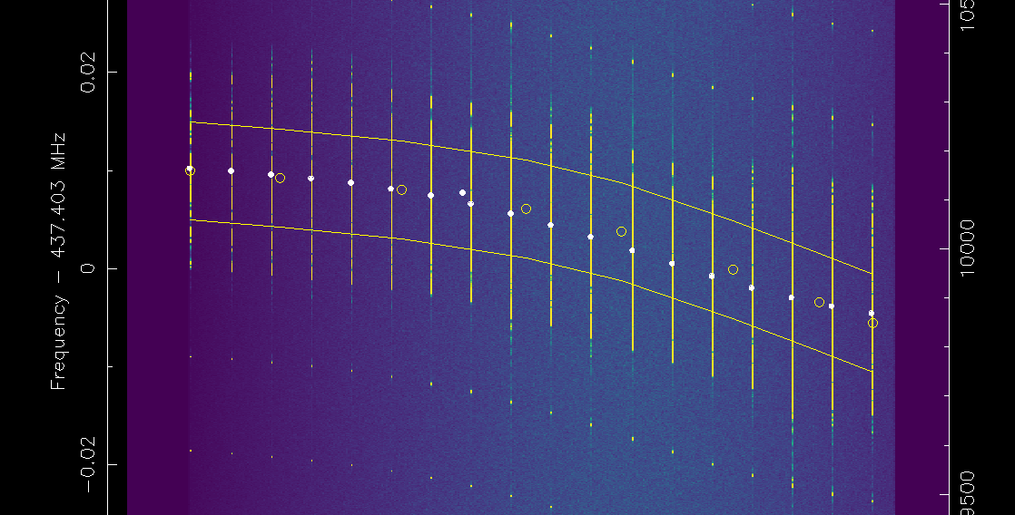
Correct residual peak finding on a modified BPSK transmission.