Cabling
Description
Repository: a WireViz source file can be placed in this directory
Releases
System Perfomance
Warning
Neither PVC bulk materials nor PVC plastic films shall be used in space applications, according to ECSS-Q-70-71A.
Note
Some wires like VBAT+ and VBAT- must be twisted. With the exception of the solar array, power lines shall be such that each line is twisted with its return, when the structure is not used as a return, as refered ECSS‐E‐ST‐20C.
System Assembly
Note
Follow the NASA workmanship guide for cable lacing. Apply this in Main harness and COMMS Programmer cable. Use cyanoacrylate glue to solidify the knots in cable.
Note
Follow ECSS‐Q‐ST‐70‐08C for cabling assembly.
Note
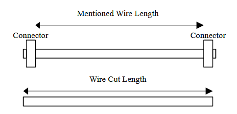
The length of the wires mentioned below correspond to the length of the cable after the assembly. While cutting the wire, please add ~ 7mm of extra length.
Color Abbreviations
RD -> Red
BK -> Black
BL -> Blue
YL -> Yellow
Wire cutting
QUBIK harnessing
WireViz Illustration
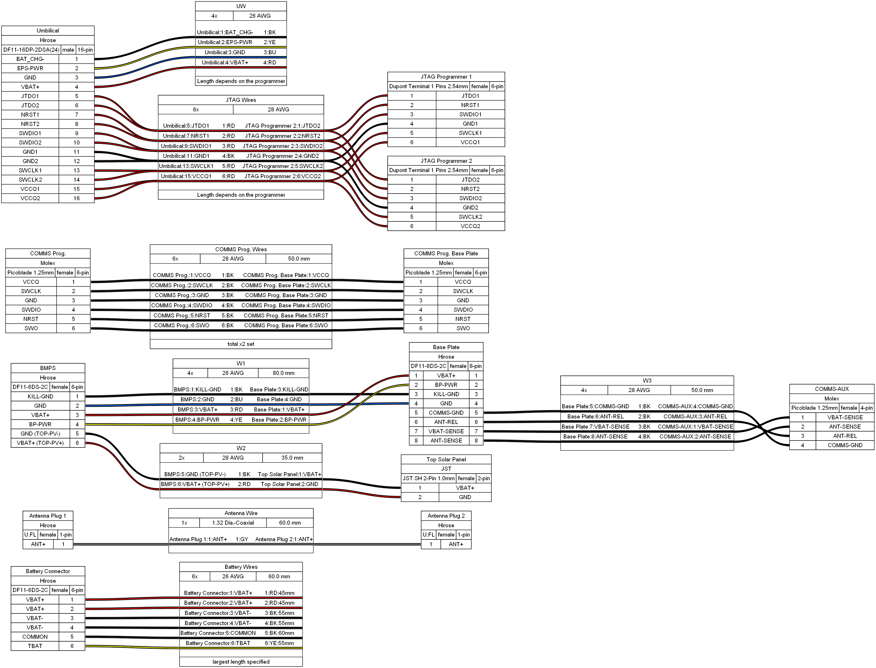
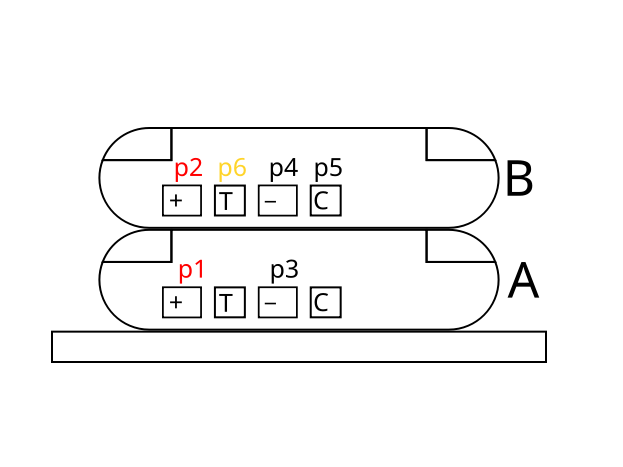
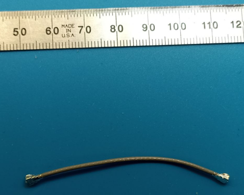
Battery cable
-
Pin 1-2: VBAT+
Pin 3-4: VBAT-
Pin 5: COMMON (which is same with VBAT-)
Pin 6: TBAT
Crimps: DF11-2428SC
Battery Cable
Note
As a convention we name (A) the battery attached on the BMPS board and (B) the other one.
Note
It is preferable to measure the colder battery, as cold is the more harsh condition for the battery performance.
Note
It is convenient to solder Common wire to (B) instead of (A).
Connector |
Pin Name |
Pin Connector |
Pin Battery |
Wire |
|---|---|---|---|---|
DF11-6DS-2C |
VBAT+ |
1 - 2 |
A(+) - B(+) |
26-AWG 45 mm (RD) |
DF11-6DS-2C |
VBAT- |
3 - 4 |
A(-) - B (-) |
26-AWG 55 mm (BK) |
DF11-6DS-2C |
Common |
5 |
A(C) or B(C) |
26-AWG 60 mm (BK) |
DF11-6DS-2C |
TBAT |
6 |
A(T) or B(T) |
26-AWG 55 mm (YL) |
Battery Stack
Antenna cable
Length: 60mm
Antenna Cable
Main harness
Connectors:
-
Pin 1: VBAT+
Pin 2: EPS-PWR
Pin 3: KILL-GND
Pin 4: GND
Pin 5: COMMS-GND (GND that no connected to in base plate GND)
Pin 6: ANT-REL
Pin 7: VBAT-SENSE
Pin 8: ANT-SENSE
Crimps: DF11-EP2428SC
-
Pin 1: KILL-GND
Pin 2: GND
Pin 3: VBAT+
Pin 4: EPS-PWR
Pin 5: GND (TOP-PV-)
Pin 6: VBAT+ (TOP-PV+)
Crimps: DF11-2428SC
-
Pin 1: VBAT-SENSE
Pin 2: ANT-SENSE
Pin 3: ANT-REL
Pin 4: COMMS-GND (GND that no connected to in base-plate GND)
Crimps: 500798001-500798020 or 500588001-500588020
JST SH Connector Female 2-Pin 1.0mm
Pin 1: VBAT+ (TOP-PV+)
Pin 2: GND (TOP-PV-)
Note
we need to cut one side and we put DF11-2428SCFA(04)
-
Connector A |
Pin A |
Pin B |
Connector B |
Wire |
Pin Name |
|---|---|---|---|---|---|
DF11-8DS-2C |
1 |
3 |
DF11-6DS-2C |
26-AWG 80 mm (RD) |
VBAT+ |
DF11-8DS-2C |
2 |
4 |
DF11-6DS-2C |
26-AWG 80 mm (YL) |
EPS-PWR |
DF11-8DS-2C |
3 |
1 |
DF11-6DS-2C |
26-AWG 80 mm (BK) |
KILL-GND |
DF11-8DS-2C |
4 |
2 |
DF11-6DS-2C |
26-AWG 80 mm (BL) |
GND |
DF11-8DS-2C |
5 |
4 |
PicoBlade 1.25mm 4-p |
28-AWG 50 mm (BK) |
COMMS-GND |
DF11-8DS-2C |
6 |
3 |
PicoBlade 1.25mm 4-p |
28-AWG 50 mm (BK) |
ANT-REL |
DF11-8DS-2C |
7 |
1 |
PicoBlade 1.25mm 4-p |
28-AWG 50 mm (BK) |
VBAT-SENSE |
DF11-8DS-2C |
8 |
2 |
PicoBlade 1.25mm 4-p |
28-AWG 50 mm (BK) |
ANT-SENSE |
DF11-6DS-2C |
5 |
2 |
JST SH F 1.0 mm 2-p |
28-AWG 50 mm (BK) |
GND (TOP-PV-) |
DF11-6DS-2C |
6 |
1 |
JST SH F 1.0 mm 2-p |
28-AWG 50 mm (BK) |
VBAT+ (TOP-PV+) |
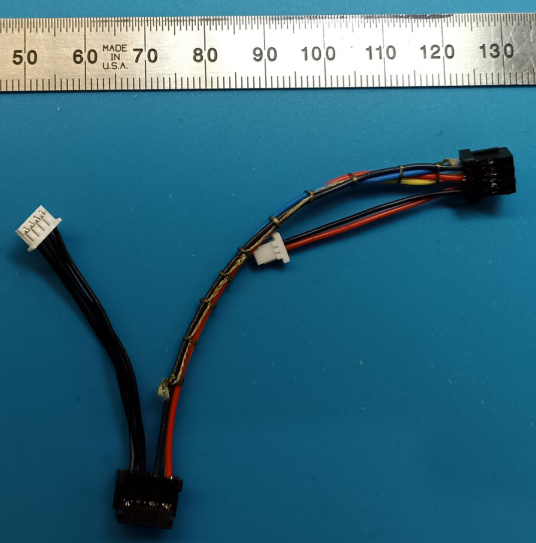
Main Harness
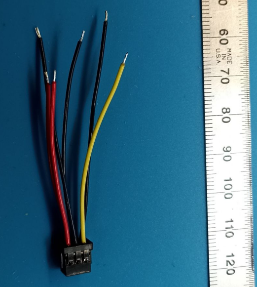
COMMS Programmer cable
Length: 50mm
1-pin is connected to 1-pin of other connector, so on one side we put new 1.25mm Pitch, PicoBlade Receptacle Crimp Housing
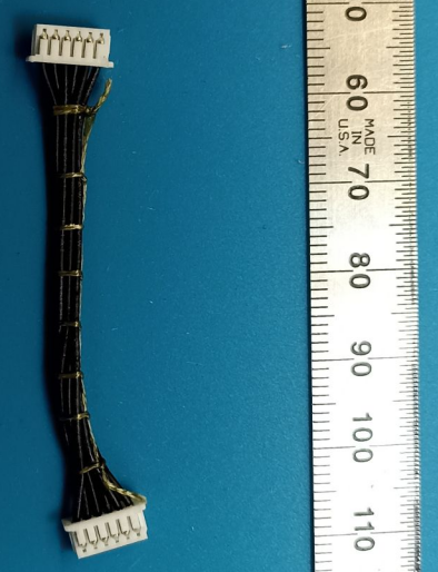
COMMS Programming Cable
Umbilical
Length: In depends on the programmer.
Pin1: VBAT-, black 26 AWG, when the switches is pushed, RBF in QUBIK
Pin2: EPS-PWR, yellow 26 AWG, when the switches is pushed, RBF in QUBIK
Pin3: GND, blue 26 AWG
Pin4: VBAT+, red 26AWG
Pin5: JTDO (COMMS), 28AWG red
Pin6: NC
Pin7: NRST (COMMS), 28AWG red
Pin8: NC
Pin9: SWDIO (COMMS), 28AWG red
Pin10: NC
Pin11: GND (COMMS), 28AWG black
Pin12: NC
Pin13: SWCLK (COMMS), 28AWG red
Pin14: NC
Pin15: VCCQ (COMMS), 28AWG red
Pin16: NC
System Testing
Related documentation:
TBD